Enabling Wi-Fi Channel 13 on the RPi in Singapore

If you are attempting to connect your Raspberry Pi to a 2.4 GHz Wi-Fi channel greater than 11 (i.e Channel 12 and Channel 13), there is a chance that the channel is not exposed to you.

/images/enabling_wifi/enabling_wifi_1.png

The reason for this is that you might not have configured your RPi's Wi-Fi Country settings. There is nothing to worry about as it's merely a configuration issue and the Wi-Fi channels have been hidden from you. To expose the channels, bring up a terminal and following the images below.

raspi-config

/images/enabling_wifi/enabling_wifi_2.png

/images/enabling_wifi/enabling_wifi_3.png

/images/enabling_wifi/enabling_wifi_4.png

/images/enabling_wifi/enabling_wifi_5.png

/images/enabling_wifi/enabling_wifi_6.png

/images/enabling_wifi/enabling_wifi_7.png

Happy hacking!

Singapore FM radio with HackRF One

It's been a while since I've posted due to different excuses. But no more, I hope to continue posting articles regularly in the spirit of learning about new technology. Today's tech gadget is the HackRF One by GreatScottGadgets. The HackRF One is a Software Defined Radio (SDR) hardware used to test and develop radio technolgies.

To keep things simple, I followed the online tutorial by Michael Ossmann and ended up with a flowgraph capable of receiving FM radio signals. I proceeded to modify the flowgraph to make the HackRF pickup all FM radio stations in Singapore. From the screenshots below, I'm guessing you can tell which is my favourite radio station.

The HackRF One is a very interesting piece of hardware and the thing I like most about is the online community. I do foresee many more interesting projects to come. One which immediately comes to my mine is to use the HackRF One to learn more about digital broadcasting in Singapore. Happy Hacking!

How do IR Flame detectors work?

As a gas turbine controls engineer, part of my job involves working with ancillary systems such as the fire and gas system. In gas turbine packages, fire and gas systems are used detect fires and flameable gases which are hazards to the operating environment.

If you are curious to know how an IR flame detector detects a fire caused by hydrocarbons, the answer is by monitoring the IR released from CO 2 and H 2 O in their excited states.

For example:

2 C 6 H 14 + 19 O 2 + Energy → 12 CO 2 * + 14 H 2 O *

CO 2 * → CO 2 + hv (2.8 µm – 4.3 µm)

H 2 O* → H 2 O + hv (2.9 µm)

Happy hacking!

/images/out.gif

Using a NPN transistor as a switch

Adding on to my post below, an NPN transistor (e.g TIP31C) can be configured to operate as an ON-OFF switch. To turn the switch ON, both V BE and V BC have to be forward biased to operate in the saturation region where transistor acts like a short circuit. To turn the switch OFF, both V BE and V BC have to be reversed biased to operate in the cut-off region where transistor acts like an open circuit.

Happy hacking!

How to differentiate the symbols of a NPN and PNP transistor?

If you've ever been confused about the conventions of the arrows of a BJT symbol, fret not cause this post aims to clarify that doubt. The arrows are used to mark the flow of conventional current through the BJT. For the NPN transitor, electrons flow from the N side to the P side, or from the Emitter to the Base, resulting in the arrow pointing from the Base to the Emitter. In the case of the PNP transistor, electroncs flow from the Base to the Emitter and therefore the arrow points from the Emitter to the Base.

A BJT has 4 regions or modes of operation, namely Active, Reverse, Saturation and Cutoff. Each region depends on the voltage bias applied to Base, Collector and Emitter of the BJT. Below is a table which nicely summiaries the different modes of operation for both NPN and PNP transistors.

Voltage relations NPN Mode PNP Mode
V E < V B < V C Active Reverse
V E < V B > V C Saturation Cut-off
V E > V B < V C Cutoff Saturation
V E > V B > V C Reverse Active

Happy Hacking!

Using a P-channel MOSFET as in Normally Close Circuit

The ZVP2110a is an P-channel Power Enhancement mode MOSFET. Having made a Normally Open circuit previously using an N-channel MOSFET, I thought why not create a Normally Closed circuit using an P-channel MOSFET. When gate-to-source voltage at -10V (source voltage greater than gate voltage), the MOSET turns ON and the LED lights up. When a control signal is applied to bring gate-to-source voltage to 0V or greater, the MOSFET turns off, in turn switching the LED off.

The table below which I took reference from here, does a nice of explaining the different modes of operation for the different types of MOSFETS.

Happy Hacking!

MOSFET Type V GS << 0 V GS = 0 V GS >> 0
N-channel Enhancement OFF OFF ON
N-channel Depletion OFF ON ON
P-channel Enhancement ON OFF OFF
P-channel Depletion ON ON OFF

Exploring the IRF510 N-channel Power MOSFET

The IRF510 is an N-channel Power Enhancement mode MOSFET used for fast switching applications such as PWM for DC motors. Here is an article I found which does a nice job of explaining how to read a MOSFET datasheet.

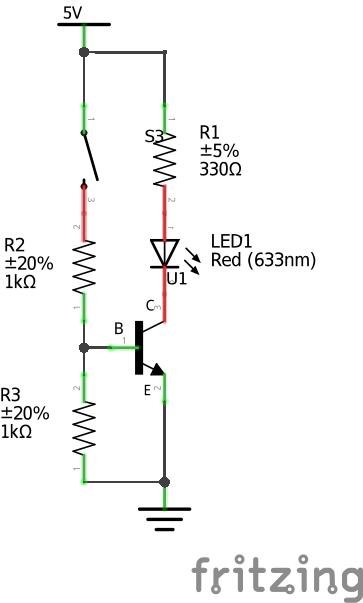
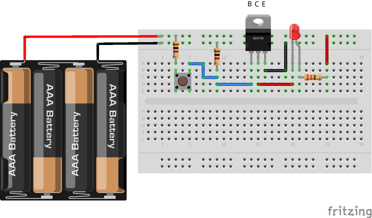
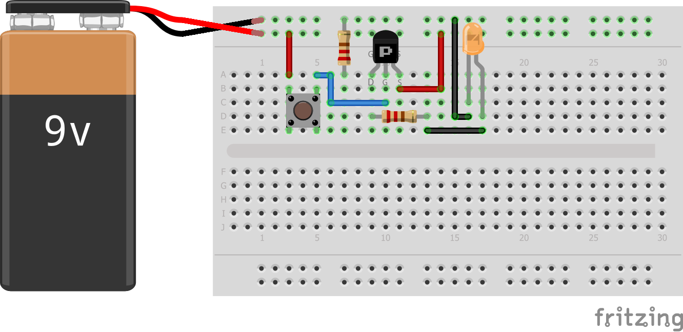
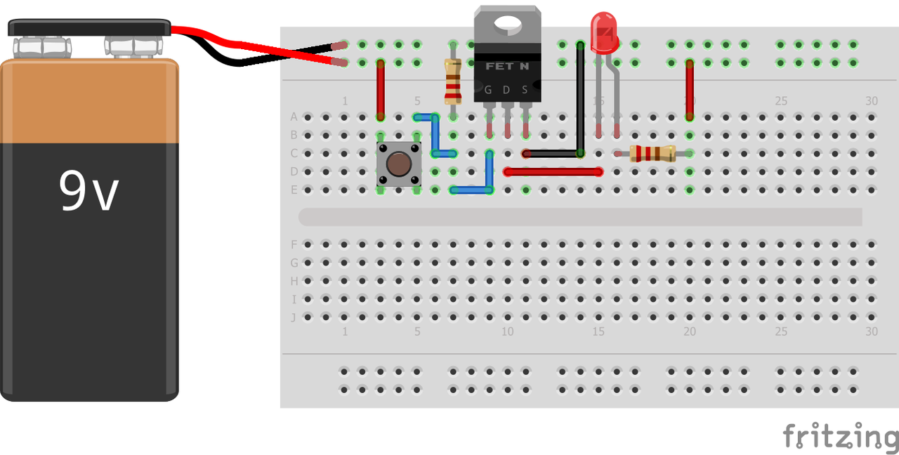
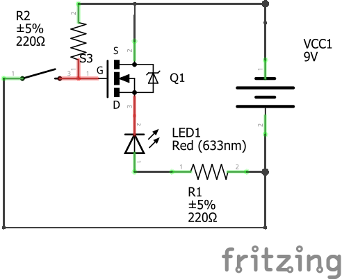
Below is a simple circuit which I created to test the MOSFET before putting it into use for PWM control of a DC motor. During operation, this circuit functions like a Normally Open circuit. When a control signal is given (e.g button is pressed), the MOSFET turns ON and the LED lights up. Technically speaking, once the gate-to-source voltage is above rated +10V, current flows from the MOSFET drain to the source. The circuit can also be term to be a current sinking circuit as the N-channel MOSFET current source sinks current to ground.

Do note that Fritzing only allows for a 9V battery but in order for the MOSFET to operate optimally as per the datasheet, you'd need a 10V voltage supply to ensure that gate-to-source voltage reaches +10V! This is in order to ensure that there is high conductivity through the channel. Running the MOSFET near gate-to-source threshold volatage (Vgth) means it has significantly higher resistance (Rd) than it would otherwise, which means a hotter FET, depending on Id.

This article does a nice job of explaining why a resistor is added to the push button in order for the circuit to function.

Happy hacking!

How to build pywin32 using python 3 64-bit on Windows 10

Most recently I had to build pywin32 from source due to a known issue on DDE (That will come under a separate post). Follow the steps to get the pywin32 64-bit built using python 3 on a Windows 10 machine.

  1. Download and run Visual Studio Build Tools 2017
  2. Select and install Windows 8.1 SDK and Visual C++ 2015.3 v14
  3. Download MFCMAPI headers. I downloaded them from http://mfcmapi.codeplex.com/SourceControl/latest, and copied EdkGuid.h and EdkMdb.h in "C:Program Files (x86)Windows Kits8.0Includeum"
  4. Download the latest pywin source code (https://github.com/mhammond/pywin32)
  5. In setup.py line 155, modify
key = winreg.OpenKey(winreg.HKEY_LOCAL_MACHINE, r"SOFTWARE\Microsoft\Windows Kits\Installed Roots")

to

key = winreg.OpenKey(winreg.HKEY_LOCAL_MACHINE, r"SOFTWARE\WOW6432Node\Microsoft\Windows Kits\Installed Roots")
  1. Run python3 setup.py install
  2. Once building is complete you will be informed that pywin32 extensions were successfully installed.
  3. The end.

DIY - Changing a USA type plug to a UK type plug

Having bought a Macbook during during my internship stint in the USA, I've always been powering it using a power extension cable which has a USA type plug. This meant that I always had to use a travel adapter. Thankfully, over the weekend I found a spare UK type plug lying around the house and decided that it was time to get the original cable plug replaced.

Stripping the cord exposed wires of 3 colours - green, white and black - which are of the NEC (US National Electrical Code) standard. Green gets connected to earth, white to neutral and black to live. Here in sunny Singapore we follow the IEC (International Electrotechnical Commission) standard where a green-yellow wire gets connected to earth, blue to neutral and brown to live. You can learn more about wiring colour codes here.

After replacing the cable plug, I was finally able to power my Mac without the need for a travel adapter.